3D Ultrasonic Concrete Imaging for Structural Assessment
Concrete is the most used construction material in the world, and much of the infrastructure built with it is aging. Bridges, dams, tunnels and nuclear structures need condition assessment without drilling cores out of them. Imaging ultrasonic testing gives inspectors a way to look inside a concrete structure and see reinforcement, voids, delaminations and cracks as two-dimensional and three-dimensional images.
Introduction
Concrete is the most used construction material in the world, and much of the infrastructure built with it is aging. Bridges, dams, tunnels and nuclear structures need condition assessment without drilling cores out of them. Imaging ultrasonic testing gives inspectors a way to look inside a concrete structure and see reinforcement, voids, delaminations and cracks as two-dimensional and three-dimensional images
This article explains how modern ultrasonic tomography instruments for concrete work. It covers the low-frequent dry-point-contact (DPC) transducers behind them, the 3D Full Matrix Capture (3D-FMC) data acquisition principle, the Total Focusing Method (TFM) reconstruction, pulse compression for very thick structures, 3D visualization modes and the measurement of crack depth.
Who wrote this
This article was written by Dr. Andrey Bulavinov, Roman Pinchuk, Andrey Samokrutov and Viktor Shevaldykin of ACS-Solutions GmbH, Saarbrucken (ACS Group). It merges two conference contributions by the same authors. The first, "New trends in the ultrasonic imaging of concrete structures by means of 3D-FMC technology", was presented at NDT-CE 2022, the International Symposium on Non-Destructive Testing in Civil Engineering, Zurich, Switzerland, in August 2022. The second, "Advanced tomographic imaging techniques for quality assessment of concrete structures by means of ultrasound", was presented at NDE NucCon 2023, the International Conference on Non-destructive Evaluation of Concrete in Nuclear Applications, Espoo, Finland, in January 2023. The authors design and build the ultrasonic tomography instruments described here. The test results shown were obtained on real reference objects, including the reference blocks of the Federal Institute for Materials Research and Testing (BAM, Germany) at the Horstwalde test site. The article text and the instrument specifications were reviewed and updated in 2026 to reflect the current generation of ACS ultrasonic tomographs.
What you'll find in this article
- How modern ultrasonic tomographs for concrete are built and why they use dry-point-contact (DPC) transducers instead of gel-coupled probes
- How 3D-FMC data acquisition and TFM reconstruction produce a three-dimensional image at every measuring position
- Why the measurement electronics and the processing unit are separated, and what this means for automated and robotic inspection
- How pulse compression extends the inspection range on thick structures, shown on a concrete block with a wall thickness of 4 m
- Which 3D visualization and rendering modes are available (Compound B- and D-scans, area scans, ISO surface, MIP, texture mapping)
- How the matrix aperture measures the depth of open surface cracks using diffraction signals
Contents
- 1. Introduction to ultrasonic imaging of concrete
- 2. Design and functional principle of modern ultrasonic testing instruments for concrete
- 3. Advanced signal processing methods to expand the testing range
- 4. Types of 3D visualization and presentation of results
- 5. Crack depth evaluation
- 6. Summary and outlook
- 7. Where ACS fits
- 8. FAQ
- 9. References
1. Introduction to ultrasonic imaging of concrete
The application of imaging ultrasonic testing of concrete in civil engineering [1] has become widespread in the last decade. The reasons for this are, on the one hand, the aging infrastructure and the increasing need for non-destructive quality assurance, and on the other hand, the significant advances in the development of testing technologies and the growing range of modern imaging testing systems on the market.
While the ultrasonic testing devices for metallic products and lightweight composite materials have a long history of use, the concrete testing devices belong to an "emerging market" in which there is still a lack of standards and regulations. Nevertheless, the modern testing instruments, with their two-dimensional and three-dimensional imaging, offer clear added value in terms of quantitative non-destructive testing and reliability of the condition assessment of the building construction.
The aim of this article is to explain the latest trends in the implementation of modern ultrasonic testing instruments for concrete testing, in particular the processing and visualization of ultrasonic measurement data, and to show the potential for expanding their area of application.
2. Design and functional principle of modern ultrasonic testing instruments for concrete
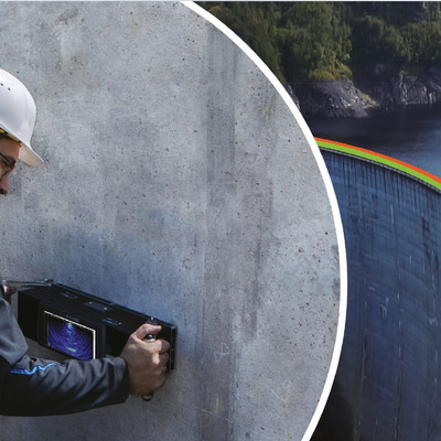
Similar to the modern ultrasonic flaw detectors for metal testing, the concrete testing instruments represent multi-channel phased array systems [2], which display the test results as images (Fig. 1).

Figure 1: Ultrasonic tomography system for concrete testing with 4 x 8 = 32 array elements.
The key element of such a testing instrument is the ultrasonic sensors. In contrast to conventional ultrasonic devices for metal testing, in which the piezoelectric transducers are coupled via a liquid coupling medium, the probes for concrete testing implement the so-called "dry point contact" principle (DPC) [3], in which a special type of excitation is used via a pin vibrating at the nominal frequency (Fig. 2).

Figure 2: Beam directivity, pulse characteristic and frequency spectrum of a DPC transducer.
Depending on the desired ultrasonic wave type (longitudinal or transverse), operating frequency and bandwidth, the construction of the transducer can vary. Broadband shear wave transducers with a center frequency of around 50 kHz are typically used for ultrasonic imaging in concrete [4].
The latest trend in the implementation of modern DPC sensors is the integration of the complete transmitter/receiver stage directly into the transducer housing (Fig. 3). In addition to the low-noise electrical properties, this design enables the excitation and reception of the ultrasonic waves with each individual element of the two-dimensional matrix aperture. In the instrument, the spring-loaded DPC transducers are grouped into a two-dimensional matrix aperture (Fig. 4).

Figure 3: Design of an active DPC ultrasonic transducer with integrated transmitter/receiver electronics (damper, piezo element, wear-resistant tip).

Figure 4: Matrix aperture consisting of the spring-loaded dry point contact transducers.
The ultrasonic data is acquired according to the so-called "full matrix capture" (FMC) principle, where the array elements act individually as transmitters and receivers (Fig. 5).

Figure 5: The principle of sequential excitation of the matrix aperture (3D-FMC). Red: spherical shear wave emitted by a single DPC sensor. Blue: spherical shear waves reflected back from the reinforcing bars or material defect.
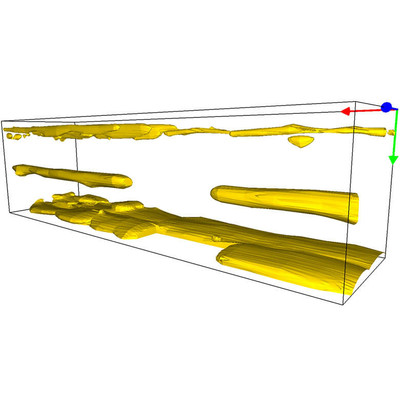
Ultrasound data originating from the two-dimensional instrument aperture consisting of 4 x 8 DPC transducers, including all 32 x 32 = 1,024 combinations of transmitters and receivers, are superposed using the "total focusing method" (TFM). The TFM method, in turn, represents a variant of the "synthetic aperture focusing technique" (SAFT), in which the aperture to be synthesized is limited to the aperture of the phased array with alternating transmitter and receiver elements. In this way, a three-dimensional image of the component volume can be generated in each measuring position of the ultrasonic tomograph (Fig. 6).
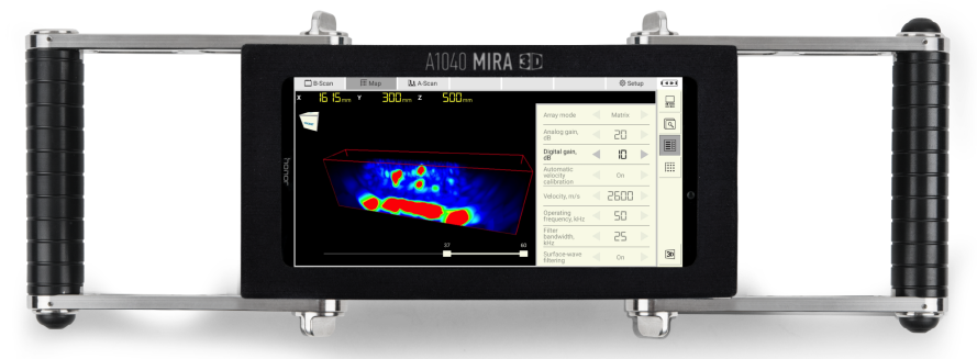
Figure 6: A 3D image of a material defect in a test position of the ultrasonic device.
Another advantage of the FMC data acquisition with the matrix aperture is the possibility of combining the array elements or several aperture blocks in any way in order to expand the near field size and thus the achievable depth of focus (Fig. 7).

Figure 7: Possible aperture combinations for 3D TFM data acquisition.
Finally, another feature of the design structure of modern ultrasonic concrete tomographs can be mentioned, which under certain circumstances can also prove to be groundbreaking for other phased array systems, for example for metal testing. The image reconstruction according to the TFM principle, in particular when calculating matrix apertures from 32 x 32 or 64 x 64 point sources, requires significant computing power in order to be able to carry it out in real time. Modern tablet PCs have multi-core graphics processors that are perfectly capable of real-time 3D SAFT reconstruction of matrix aperture data.
The function of the data acquisition electronics is limited to the excitation and reception of the ultrasonic signals, as well as digitization and transfer of the raw ultrasonic data via a WiFi data interface. The entire data processing (including digital filtering), image reconstruction, visualization and evaluation (including reporting) is taken over by a high-performance tablet PC or, alternatively, a desktop or laptop computer (Fig. 8).

Figure 8: Communication of the measurement electronics unit with various processing units.
The advantages of such a separation of the measurement and processing electronics and their wireless communication are, among others:
- A less expensive version of the measurement electronics
- Flexible further development of the application software (APP) without "intervention" in the measurement electronics
- Automatic advantages thanks to new generations of computing units with improved performance
- A wide range of options for automated recording of ultrasound data, for example when integrating the ultrasound device into a scanner unit with remote control
The separation of the DAQ and processing units communicating wirelessly opens the opportunity for automated implementation of the ultrasonic testing procedure, where not only the UT instrument but also the scanning robot are remotely controlled by the operator (Fig. 9).
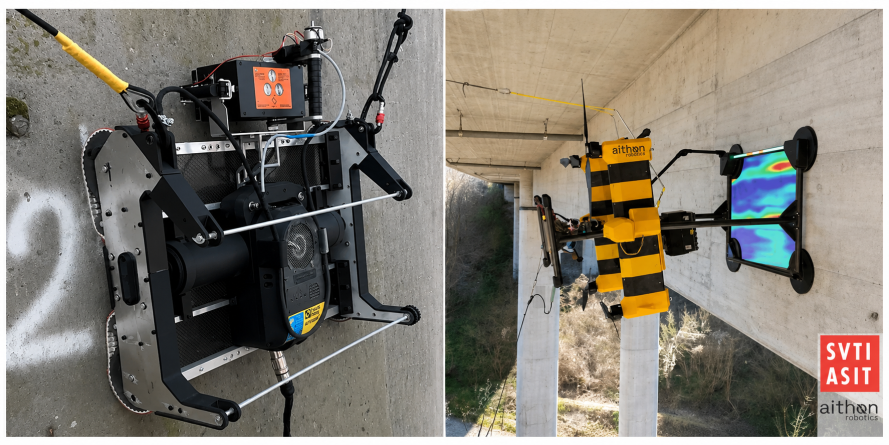
Figure 9: Possibility of automated data acquisition by crawler robot (HausBots LTD) and inspection drone (SVTI ASIT) via the wireless data interface.
3. Advanced signal processing methods to expand the testing range
One of the unique features of the ultrasonic instruments for concrete testing compared to other testing methods, such as ground penetrating radars, is their greater range with high resolution. Even when testing reinforced concrete, an inspection range of up to two meters can be implemented (Fig. 10).

Figure 10: B-scan representation of a heavily reinforced concrete object over the range of 1.1 meter.
Nevertheless, ultrasonic testing also has its physical limits if the material to be tested has increased sound attenuation, for example due to coarse aggregates, or if particularly thick structures, such as dams, with a wall thickness of several meters are being tested. The insufficient signal-to-noise ratio does not allow the recorded ultrasonic signals to be evaluated.
If you look at the raw ultrasonic echo signals in detail, you can divide the signal noise into three categories:
- Coherent acoustic noise due to ultrasonic backscattering
- Quantization noise due to the limited resolution of the analog to digital conversion
- Thermal noise
The last two types of noise occur, in particular, with very long sound paths, where one has to deal with relatively weak signals despite increased amplification values. This can be successfully overcome using a so-called pulse compression technique. For this purpose, instead of a short monochromatic excitation sequence, a long modulated excitation sequence is used to excite the ultrasonic waves, which is then extracted again in the received and digitized ultrasonic signal. As a result, a significant improvement in the signal-to-noise ratio and the spatial resolution can be achieved (Fig. 11).

Figure 11: Schematic representation of the types of noise (left) and the suppression principle using a modulated excitation sequence (right).
As a result of such a decomposition of the received echo signals before the SAFT image reconstruction, a denoised test result is obtained (Fig. 12).

Figure 12a: Measurements on a concrete block with a wall thickness of 4 m.


Figure 12b: Test results on the 4 m concrete block without and with the pulse compression technique.
The results in Fig. 12 were obtained on the reference object of the Federal Institute for Materials Research and Testing (BAM) at the BAM-TTS test ground at Horstwalde, Brandenburg.
4. Types of 3D visualization and presentation of results
The transition from the implementation of the line array principle to the matrix array principle offers new options for the visualization of ultrasonic test results. As an "elementary" data set in a test position, a three-dimensional volume data set is used for each recording, which has an improved spatial resolution compared to linear array devices. This is thanks to the implementation of the 3D TFM principle. Of course, this requires a more complex hardware implementation, such as a fully parallel design of the ultrasound channels and computationally intensive 3D SAFT reconstruction.
This means that three-dimensional data sets (Panorama B-scan and Panorama D-scan) are created for any type of component scanning with equidistant measuring points, both in the X and Y directions (Fig. 13), which are visualized so that three side views (B, C and D scans) are respectively displayed. If the data is recorded in two-dimensional MAP mode with both scan axes X and Y, volume data sets (area scans) of any size can be created. These require appropriate tools, such as zooming and scrolling, for their display representation.

Figure 13: Volume display modes when visualizing the ultrasound data (single 3D scan, Panorama B-scan, D-scan, C-scan top view, AREA scan).
Depending on the application, the actual visualization of the voxel data can be done in different rendering modes (Fig. 14): ISO surface, Maximum Intensity Projection (MIP), texture mapping and B/C/D gated volume MIP.

Figure 14: 3D rendering modes for the reconstructed volume data. a) ISO surface, b) Maximum Intensity Projection (MIP),
c) texture mapping, d) B/C/D gated volume MIP.
5. Crack depth evaluation
Another significant advantage of the matrix aperture with extremely small single array elements is its very broad beam directivity characteristic, which, among other things, allows acquiring diffraction signals from unfavorably oriented material flaws, such as the tip of an outwardly open crack. This makes it possible to determine the depth of such material defects without being able to insonify them "frontally".
When performing such a measurement, it is necessary that the number of DPC sensors on both sides of the open crack is equal and that the crack depth does not exceed the overall aperture size of the device (Fig. 15).

Figure 15a: Arrangement of the instrument aperture in relation to the crack (left) in the crack depth measurement mode of the ultrasonic tomograph (right). The crack tip acts as the source of the diffraction signals.

Figure 15b: Measurement of a natural crack depth in the structure.
6. Summary and outlook
This article presented current trends in the implementation and application of imaging ultrasonic testing systems for non-destructive concrete testing. These mainly consist of the application of the matrix apertures based on active DPC ultrasonic transducers and the implementation of three-dimensional FMC/TFM methods for tomographic imaging. Among other things, this sensor design allows the use of pulse compression techniques when exciting the ultrasonic waves and thus a significant expansion of the realizable inspection range to several meters.
The transition from the conventional line array principle to the use of matrix apertures allows three-dimensional tomographic imaging with improved spatial resolution in every position of the ultrasonic tomograph and the implementation of special functions for quantitative defect assessment in the near field of the ultrasonic sensor system, such as evaluating the crack depth. The full conference versions of this material are available as references [5] and [6].
Where ACS fits
The methods described in this article are not laboratory concepts. They are implemented in the ultrasonic tomography instruments we build at ACS Group. The A1040 MIRA 3D family uses a matrix aperture of active DPC transducers with 3D-FMC data acquisition and real-time TFM reconstruction on a wirelessly connected processing unit. The base instrument works with the 4 x 8 aperture of 32 elements described in this article, and the A1040 MIRA 3D PRO extends the aperture to 64 elements and more. The pulse compression mode for thick structures is implemented as the E-Boosting function, and the crack depth measurement mode described above is available on the instrument.
The reason we develop both the transducers and the reconstruction software is the same reason this article covers both. The image quality of ultrasonic tomography depends on the whole chain, from the contact point of the sensor to the rendering of the reconstructed volume. More articles like this one are collected in our technology library.

Frequently Asked Questions
What is 3D-FMC in ultrasonic concrete testing?
3D-FMC stands for three-dimensional Full Matrix Capture. Each element of the two-dimensional matrix aperture transmits in sequence while all elements receive. For a 4 x 8 aperture this gives 32 x 32 = 1,024 transmitter-receiver combinations, which are then superposed with the Total Focusing Method (TFM) into a three-dimensional image of the component volume at every measuring position.
How deep can ultrasonic tomography see in concrete?
An inspection range of up to two meters can be implemented even in reinforced concrete with standard excitation. With pulse compression, where a long modulated excitation sequence replaces the short monochromatic pulse, the range extends to several meters. The results shown in this article were verified on a concrete block with a wall thickness of 4 m at the BAM test site at Horstwalde. The current instrument specifications state a maximum penetration depth of up to 3 m in reinforced concrete for the A1040 MIRA 3D and over 4 m for the A1040 MIRA 3D PRO with the E-Boosting technique.
Why do concrete testing probes not need couplant gel?
The probes use the dry point contact (DPC) principle. A wear-resistant pin vibrating at the nominal frequency transmits the ultrasound into the concrete through a single contact point, so no liquid coupling medium is required. The spring-loaded transducers adapt to rough concrete surfaces.
What is the difference between TFM and SAFT?
TFM is a variant of the Synthetic Aperture Focusing Technique (SAFT) in which the aperture to be synthesized is limited to the aperture of the transducer array, with alternating transmitter and receiver elements. In modern concrete tomographs the 3D TFM reconstruction runs in real time on the graphics processor of a tablet PC.
Can ultrasonic tomography measure the depth of a crack?
Yes, for outwardly open cracks. The broad beam directivity of the small matrix array elements picks up diffraction signals from the crack tip, so the crack does not need to be insonified frontally. The measurement requires an equal number of DPC sensors on both sides of the crack, and the crack depth must not exceed the overall aperture size of the device. This measurement is implemented as a dedicated crack depth mode in the A1040 MIRA 3D ultrasonic tomograph, which evaluates the depth of open surface cracks with one-side access directly on the instrument.
What is the advantage of ultrasound over ground penetrating radar for concrete?
The greater range with high resolution and higher sensitivity to material defects (cracks, honeycombs, cavities, grouting defects). GPR is a widely used method for locating objects in concrete, but the ultrasonic instruments described here reach up to several meters in reinforced concrete, while keeping the sufficient sensitivity and spatial resolution needed for defect detection and evaluation.
References
[1] V.N. Kozlov, A.A. Samokrutov, V.G. Shevaldykin. Thickness measurements and flaw detection in concrete using ultrasonic echo method. Nondestructive Testing and Evaluation 13(2): 73-84, January 1997.
[2] V. Shevaldykin, A. Samokrutov, V. Kozlov. Ultrasonic low-frequency short-pulse transducers with dry point contact. Development and application. International Symposium Non-Destructive Testing in Civil Engineering (NDT-CE), 16-19 September 2003. Journal of Civil Engineering and Management, 2013, 19(6): 775-786.
[3] A.O. Haza, C.G. Petersen, A. Samokrutov. Three-Dimensional Imaging of Concrete Structures Using Ultrasonic Shear Waves. German Instruments SA, Denmark, 2011.
[4] A. Bishko, A.A. Samokrutov, V.G. Shevaldykin. Ultrasonic echo-pulse tomography of concrete using shear waves low-frequency phased antenna arrays. Proceedings of the 17th World Conference on Non-Destructive Testing, 2008.
[5] A. Bulavinov, R. Pinchuk, A. Samokrutov, V. Shevaldykin. New trends in the ultrasonic imaging of concrete structures by means of 3D-FMC technology. NDT-CE 2022, International Symposium on Non-Destructive Testing in Civil Engineering, Zurich, Switzerland, August 2022. DOI 10.58286/27285. Also published on acs-international.com.
[6] A. Bulavinov, R. Pinchuk, A. Samokrutov, V. Shevaldykin. Advanced tomographic imaging techniques for quality assessment of concrete structures by means of ultrasound. NDE NucCon 2023, International Conference on Non-destructive Evaluation of Concrete in Nuclear Applications, Espoo, Finland, January 2023.